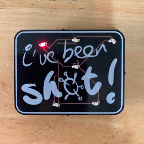
Back in January, when I was pondering my Jan-Feb project (for my year-long challenge), members of my family were starting to get vaccinated. Since I’ve been trying to do projects that represent things or have meaning, I tried to think of something that would ‘represent’ aspects of immunology, RNA, viruses, and vaccines. Alas, I couldn’t. So I figured I’d do a badge.
More leveling up
I’m always trying to do something new. I’d done a few PCBs. I was comfortable using an ATtiny to animate an LED. So I wanted to push a few things here.
First of all was the artwork. My mother has an iPad with a pen, so I drew out a few iterations of ‘I’ve been shot!’. Then I took it all into Inkscape to take advantage of svg2shenzhen, a cool plugin that I wish I had the first time I tried to make art PCBs about a year ago.
Then, for the circuit, I wanted to use an ATtiny85 or, my favorite, ATtiny45. And to maximize the number of LEDs, I decided to Charlieplex them, and use the RST pin to cycle thru animation (state memorized by EEPROM). To add a fun twist, I thought I’d use one of the new ATtiny 0-series chips, the 402. The chips are close enough to what I know, but would require a new programmer (it uses UPDI instead of the usual ISP programming). New! So part of this project required me to build a UPDI programmer.
Also, because it was going to be all surface mount components, I bought some solder paste (in a syringe) so I could try soldering with my hot gun (a new technique for me).
Chugging along
All was going well. I prototyped the Charlieplexing and code on an ATtiny45. Was able to easily design the board in KiCad, with the artwork. Ordered the boards from Oshpark in the After Dark style. And picked up parts from Digikey, as I usually do.
Soldering went well. Maybe one LED spun around and ended up backwards. But Charlieplexing is forgiving – it still it up, but at the wrong sequence.
But something big came up when I was programming the chips prior to mounting – I found out that the UPDI and RST pin are not shared (ugh, a reminder to always prototype with new chips before building with them). I knew UPDI and RST were on the same pin, but I didn’t know you could only have one or the other. Aaaand, if you set the UPDI pin to RST, you need a High-Voltage (HV) programmer. So once you set the bootloder to set the fuses to use the RST instead of UPDI, you need a HV programmer to load your sketch.
I was stuck. The board was designed to do the RST with the RST/UPDI pin. So there was no way the board was going to work. As insurance, then, I set another pin to be used as reset (a slightly different interrupt coding than with the ATtiny45s, but seemed cleaner).
In the end, I had fully assembled badges, with the right code and backup interrupt pin, but which wouldn’t work as wired. I could cycle thru the animations by pulling out the battery and reinserting, or by using a wire to ground the backup pin.
That’s OK. I’ll just buy a HV UPDI programmer.
High-voltage frustration
The guy on Tindie with the recommended one was out of stock and despite pestering him and waiting more than a month, he never made more, even tho he said he was about to. Fortunately, the guy (who is really clever and documents things well) made everything available to buy the boards (from Oshpark) and build the HV programmer yourself. So that’s what I did.
I don’t know. I built the HV programmer, but was never able to get it to do HV programming (it did regular UPDI programming quite well, but I already had a programmer to do that). After wanting to do this for almost two months, buckling down and spending some money to get more than I needed had I been able to just buy it on Tindie, I threw in the towel trying to reprogram the chips on my badges.
One last try
I have lacquered wrapping wire – it’s nice and thin and comes insulated. Perfect for a bodge.
And I see so many folks (*cough* Greg Davill) doing amazing bodges, I realized that my only way to make these badges usable was to try a badge with the lacquered wire. So decided to give the project one last effort and to try to bodge the badges.
Now, I had thought the soldering process would be enough to burn off the lacquer to expose the copper. But I found out (after not being able to make the bodge work) that it takes time. So I patiently bubbled off the lacquer (checked it with a multimeter) and bodged all the badges.
It worked. I hot-glued some pins to the back and now have a proper badge to hand out to vaccinated family members.
Summary
On a whim, I designed a badge to commemorate getting a COVID-19 vaccine. I managed to compete this project within my Jan-Feb time frame. Except for one wrinkle. Along the way, I tried some new things for me, but walked into an unexpected feature of the new chip I used. I tried one way to fix it, but was stymied, until I figured out how to do a simple bodge.
Yay.
One more thing: aside from missing the UPDI/RST issue, I was schooled again on sizes. Man, 0805 is small. And so is SOIC-8. But I knew that already. The real head-scratcher was the 3mmx5mm button. Gosh, that’s small. I really need to just buy a bunch of buttons to try out and get a feel for. Haha.
1 Comment
Comments are closed.