This is a chapter from a book I wrote during NanoWriMo 2011. The story was about folks who ‘shepherded’ marine mammals and fish (with the aid of dolphins, hence the dolphin reference below). Interspersed in the story were short chapters, interludes of unspecified origin – dreams? digressions? thoughts? This is one of them, pertinent to a recent, previous, post on technology, hence why I am sharing this now.
Pocket Universe
I was amazed by how fast nothing happened.
The sun hung for hours in the same spot, smiling from the clear blue sky, causing the raft to hum with vivid orangeness. The water gently lapped and rocked the raft, and the mild breeze took me in a direction I only had a vague idea might have been where I wanted to go.
I didn’t think of my dolphins, but I did, and wondered where they were. I’d been here so long, I no longer remembered why. All I could remember was that the sun hadn’t moved in a long time and my life vest chafed at my neck. And the overalls were hot too, their dark fabric absorbing the sun’s heat, almost burning.
I kept counting the seconds to 60 but kept forgetting to count how many times I’d gone around. I think time had run out of minutes, and I was stuck with just seconds. Each time I hit 60, I started back at 1, instead of marching on to 61 or 6001.
It must have something to do with the sun not wanting to budge from her spot.
I shifted a bit and I felt something in my pocket.
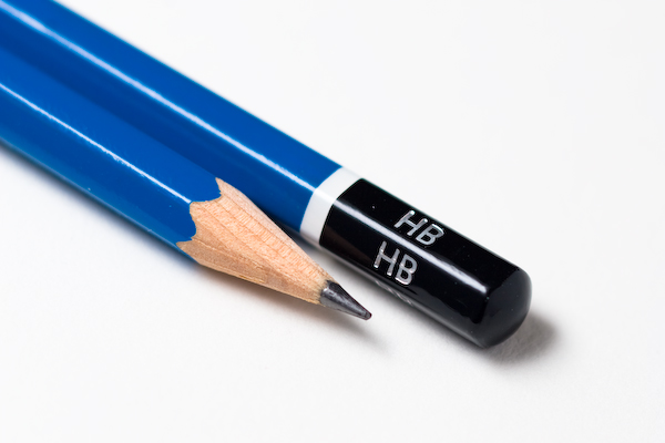
A pencil. Yellow. The standard hexagonal American kind with metal collar holding a red rubber eraser. The pencil was nice and factory sharp, with a bit of fine saw dust still around the grey graphite tip.
It was an amazing graphite tip.
I could almost see the atoms dancing on the tippy tip.
A pencil is made of many parts, and each part has its origin story. There’s the paint, print, metal ring, rubber eraser, wood case, and lead. Each one has its origin and use, and this simple yellow pencil is the product of complex material manipulations, chemistry, extrusions, cutting, mixing, rolling, sanding, painting, handling, wrapping, shipping, and moving until it’s an object to be fondled under a stationary sun in the middle of the Pacific.
ISN’T THAT JUST MIND-BLOWING? Never mind worrying if anyone will find me in the middle of nowhere, I have a PENCIL that is more amazing, Alyosha, than all of your philosophies. It’s the manifestation of the Universe all wrapped up and ready for a wee kid to doodle with. It’s the Universe hidden in the mundane. It’s the bloomin’ magical Universe, styoopid, and it’s right under your fat nose. And no need to invoke any higher power, neither. It’s a pencil. You and I can make one.
You’ll need a casing – fragrant cedar is my favorite – cut into slats from blocks and blocks of the finest wood, down to a small bed with a groove to intimately sandwich, hold, and enfold the pencil lead like a precious woman in her lover’s arms. And the lovers – casing and lead – are shot through a planning process that adds multiple facets to their relationship, in the case of the yellow object in my hand, six facets (Hm, what might those facets represent? – family, children, society, friends, work, death, money – no, that’s seven, are there seven-sided pencils? I digress.)
And then the polished and burnished pencil casing is painted and lacquered multiple times (sure would be less times if it weren’t mechanized) for children everywhere to ingest chips of while chewing, holding, handling these blessed, Universe-on-a-Stick, pencils.
Regarding pencil lead: There’s no lead in pencil lead. Pencil lead is made of graphite, made of the same stuff diamonds are, and fullerene, if you’re particular. Therefore, you didn’t get poisoned in school when you aggravated your friend and she poked you in anger and broke the lead tip in the palm of your hand. (OK, I, I didn’t get poisoned.)
The folks who are to blame for this misconception were, presumably, pre-Chemistry, when it was thought that graphite chunks looked a lot like lead. Though, I have more respect for ancient chemists than most and am pretty sure they could tell the difference – c’mon, lead is HEAVY.
But the pencil lead, I mean, pencil graphite is not pure graphite, but mixed with clay for different hardness and darkness. The mixture itself is ground and pressed into long cylinders and then kiln dried, carefully so as not to damage the lead. So next time a svelte boho artiste designer-type asks you if she makes you BBB or HHH, give her a knowing grin.
But we’re not done, you need to let the world know you made the pencil, and so with the lightest foil and hardest punch, you imprint whatever you darn well please on the side of that pencil, around it if you wish (it is you making the pencil, after all), and then send it off to get it’s crown of rubber and metal.
I looked up and the sun still had not moved. In protest, I tilted myself, just so that my shadow would take on a different angle. If the sun won’t move my shadow, then I will take full responsibility.
The sad thing is that this pencil is mass produced. Also, most of us only think of the “How they make it” part. But it’s much deeper than that.
Graphite is not just some soft carbon material used for steelmaking, brake linings, lubricants, or, of course, pencils. It’s a hexagonal crystal of dihexagonal dipyramidal symmetry. Crystalline symmetry! And it’s the most stable form of carbon, to boot (or is that, “to soot”?)
If I look closely at the pencil point, I see the mixing of the clay and graphite. Getting closer, I can see the phyllosilicates of the clay next to the dihexagonal dipyramidal of the graphite. And getting closer still I see – well, it’s really interesting what I see.
We’re so trained in the balls and stick model of atoms and molecules, but when I get down to this level, it’s really not the same. Each atom is a force field, filled with electrons (Carbon has six in three different orbitals – and no, I don’t mean electrons spinning around the nucleus like planets, but electrons spinning about on their axes moving about in a defined area, captured – argh, it’s really hard to explain sub-atomic wonders via macro-atomic imagery; that will make more sense as I push closer)
As I push farther, into all the shells, the orbitals, I can see the nucleus, a dense knot of protons and neutrons. These two defy explanation, as, to me, they are just bundles of energy. But I am not going to stop there; I’ll plow into a proton where there are even smaller tangles of energy – two up quarks and one down quark.
At this level, I find it meaningless to talk about elemental particles. They are just fluctuations in the fabric of the Universe, braille bumps that somehow are stable, join up into higher order structures, and higher, and higher – oh, I’m back at my pencil lead tip.
I look up. The sun still hasn’t moved. I’ve traversed the whole of Creation on a pencil and the sun doesn’t have the courtesy to move. This day will never end.
I can hear the photons taking their eight and a half minute journey from the surface of the sun, through space, to slam into my face, tripping photo sensors, causing a cascade of genes to produce melanin, making me feel happy, and setting my sleeping clock.
I can taste the blue of the sky, full of wispy water, neutral nitrogen, obnoxious oxygen, and a smattering of argon and carbon dioxide and a few other gasses. Mmm.
I am buoyed on the orangeness of my raft, its brightness a hand lifting me up, caressing me, protecting me from the water, gently rocking me to sleep.
Damn, that sun hasn’t moved. The nothing is happening faster than I can keep up with it.
Image from Wikipedia