Here is my final project of my year-long challenge. I was on target to finish it on time, but life has a way and I ended up finishing it about a week late. But fluid timelines were common to this year-long challenge. Plus, I really didn’t start this last project on time.
Clear vision
As with some of my projects, I had a clear vision of the face of this project. Well, sort of. I knew I wanted a tree image and pixels for leaves going through the seasons. And part of my prep for a project, I think of a ton of things, such as, in this case, looking up tree lifecycles as reported by some service or some freeform sculpture.
If there’s one thing I learned in the past year doing these projects, though, is to mind the feature set and the time frame. I also wanted to keep in mind what I could do with minimal purchasing. An earlier project had exceeded my usual burn rate.
The tree
With a clear desire for a tree, I figured I could draw something or get a SVG online to convert into a 3D model. Though, remembering my COVID model, I dug a bit deeper to see if I could find a ready-made model
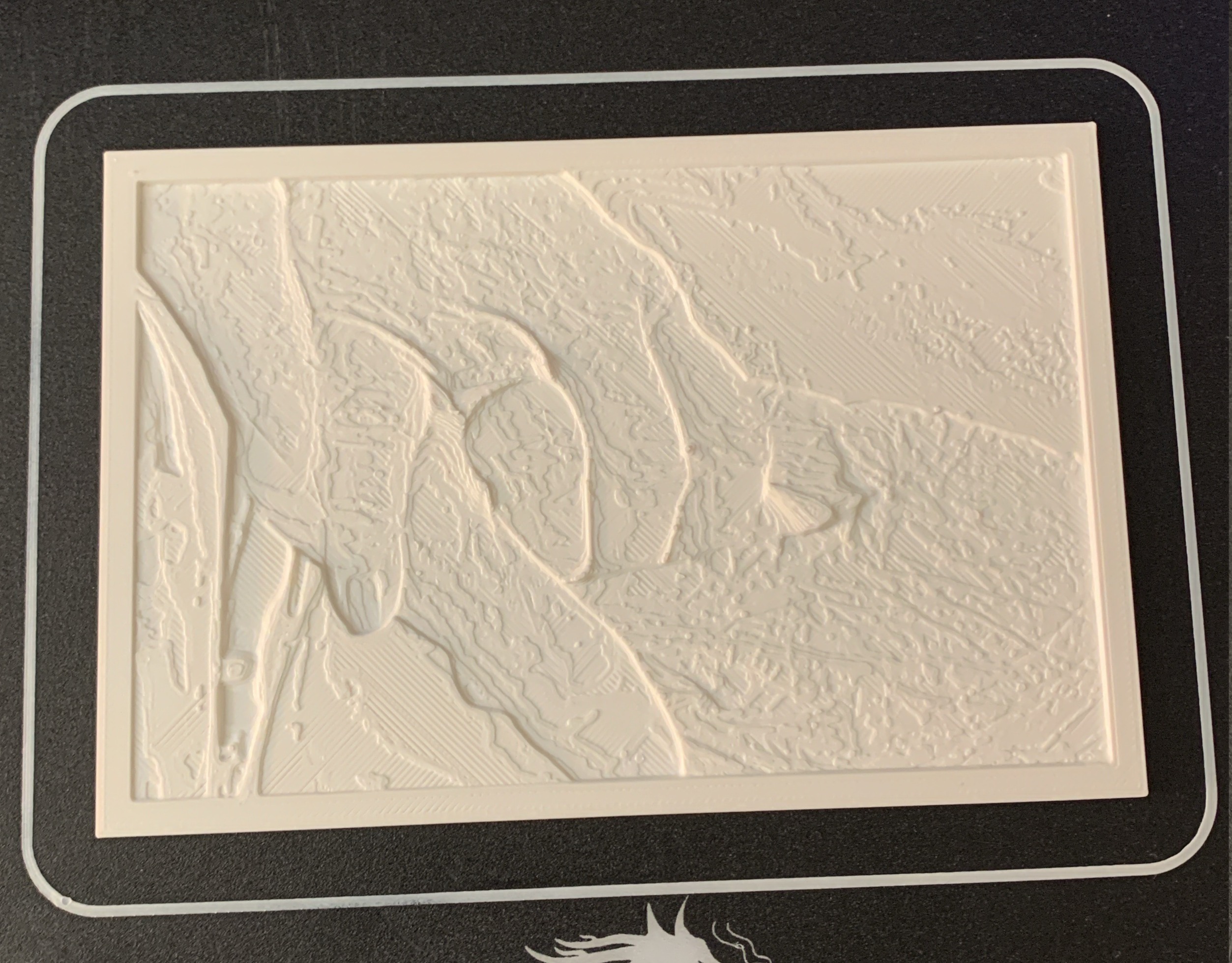
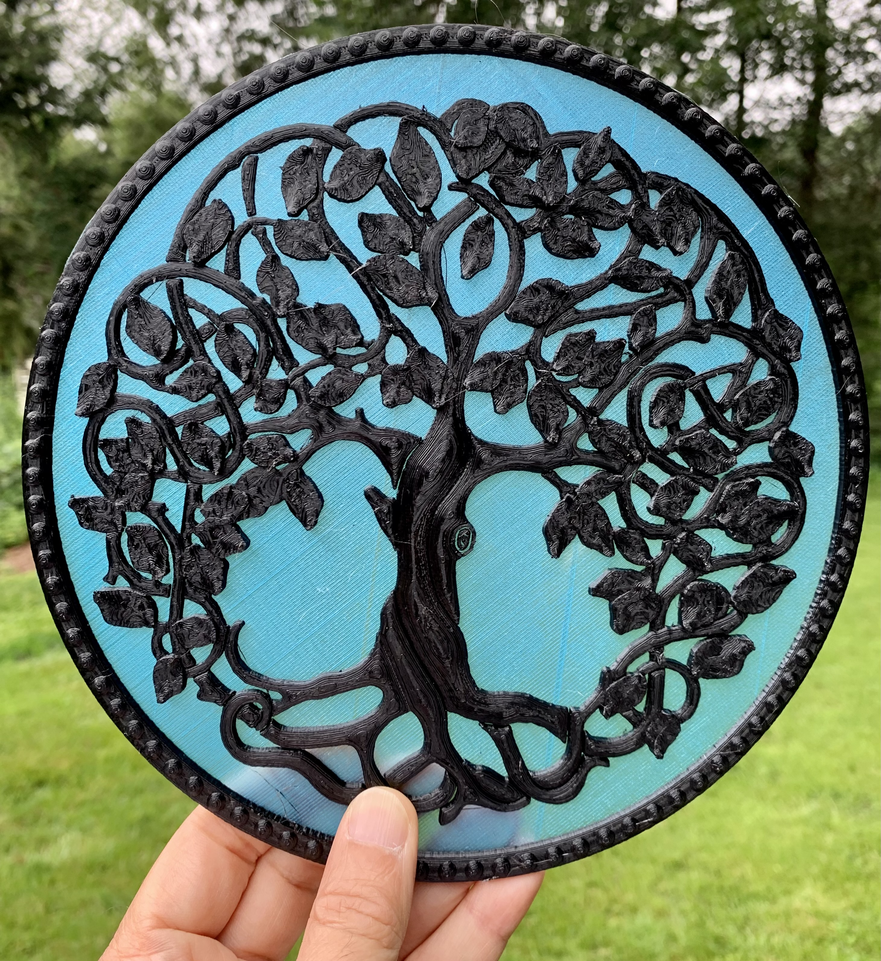
Unfortunately, so many were indeed just a flat conversion of an image into something for a CNC or a 3D printer. But then I found (and bought) a really intricate model, meant for a CNC, with precisely the aesthetics I was searching for (see below). And the model maker was kind enough to convert it for 3D printing.
I printed a small version to see what it looked like and it came out nice. Though, my 87-year old maker mom took one look and suggested I print it out in two colors. Which was a great idea.
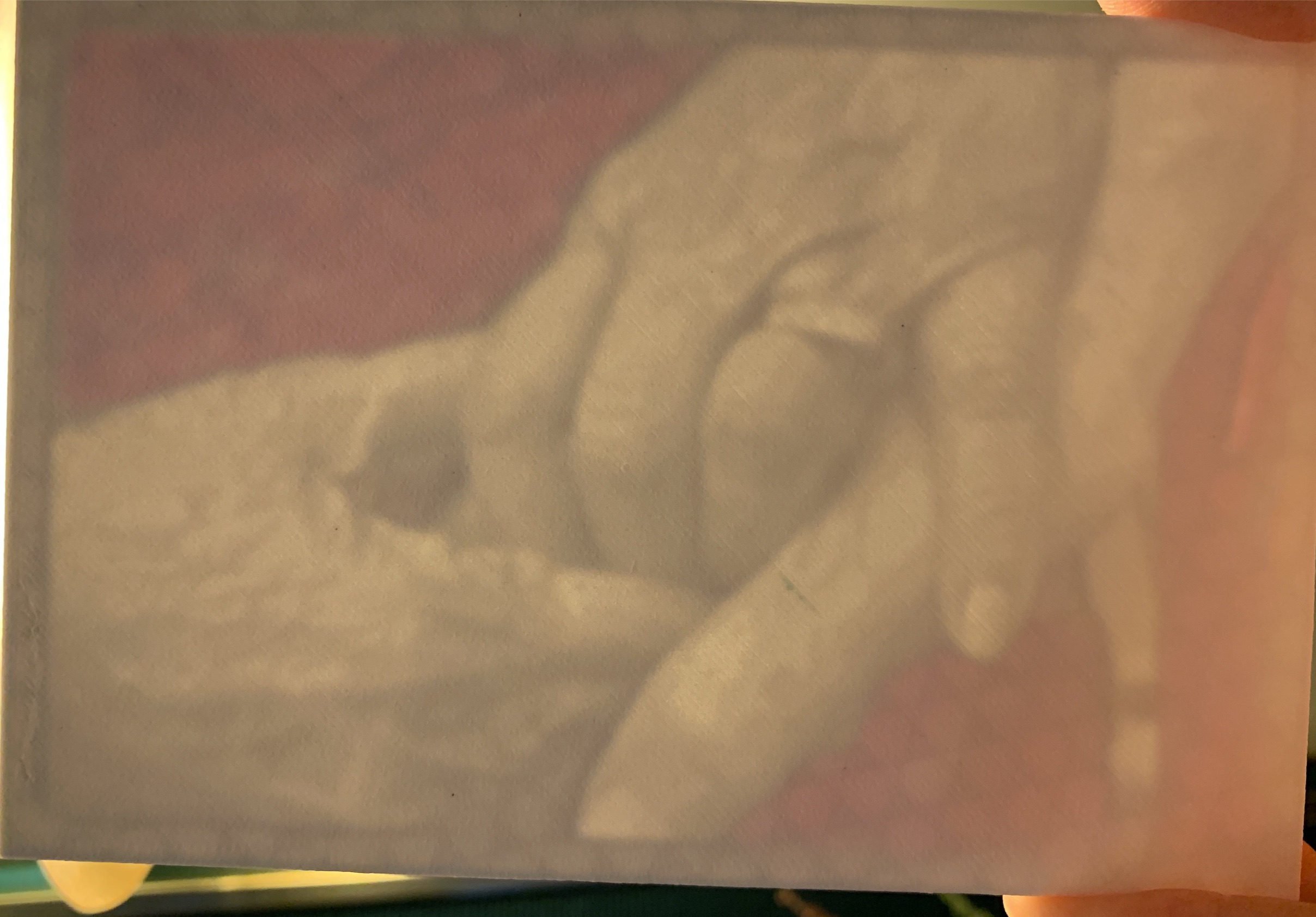
I had originally thought of poking the neopixels through the model, but when she suggested two colors, I knew it had to be something translucent. So I then did a sample print with the red translucent filament I had. To which, of course, my mother suggested I try a different color.
I picked up a baby blue translucent filament and whipped up another test print. It looked great. Just the look.


Trouble in model-land
My next move was to modify the print. Initially, I was thinking of poking the neopixels through, but with the translucent part of the print, decided to modify it so that I could mount it on something.
Turns out this model was way complex and Fusion 360 (or at least the copy I had) was choking on it and requiring that I lower its resolution. I spent a few hours wrangling with it, but no luck. So I had to change my tactics – I decided to make a ring that I’d then glue to the model and then screw that to the backing that would hold all the electronics.
Getting on with the printing
After printing some test prints to make sure I was making the backing properly, I printed up all the parts – the ring, the backing, and the tree.
The full-size tree print was about 16 hours, including the filament change after the first few clear layers.
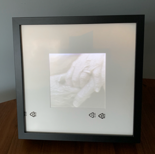
Came out so nice.
For the backing and ring, I made a simple model in Tinkercad (where I prefer to make my simple models).
The idea was to solder a string of neopixels and glue them and the microcontroller to the backing. But I had specific places to put the pixels, so I printed a paper copy of the tree, marked where I wanted the pixels, flipped it over, put down some two-sided tape, measured the wiring, and soldered the neopixels together stuck to the places I had marked. [If you wonder why flipped over, it’s because I had to solder the back of the pixels.]
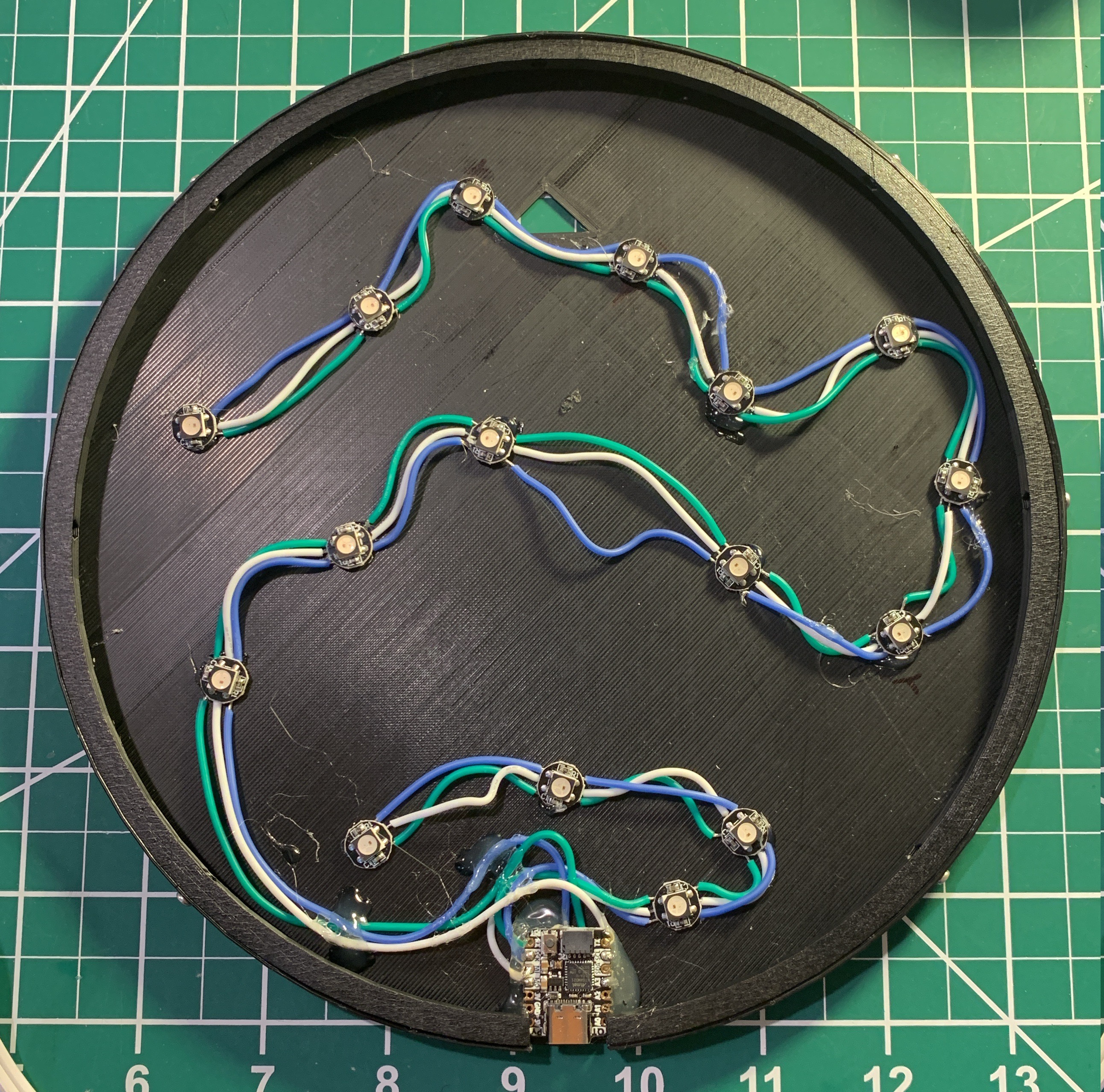
To then transfer the neopixels to the backing, I then flipped it all over and put it in the backing, slowly gluing the pixels and removing the paper and tape.
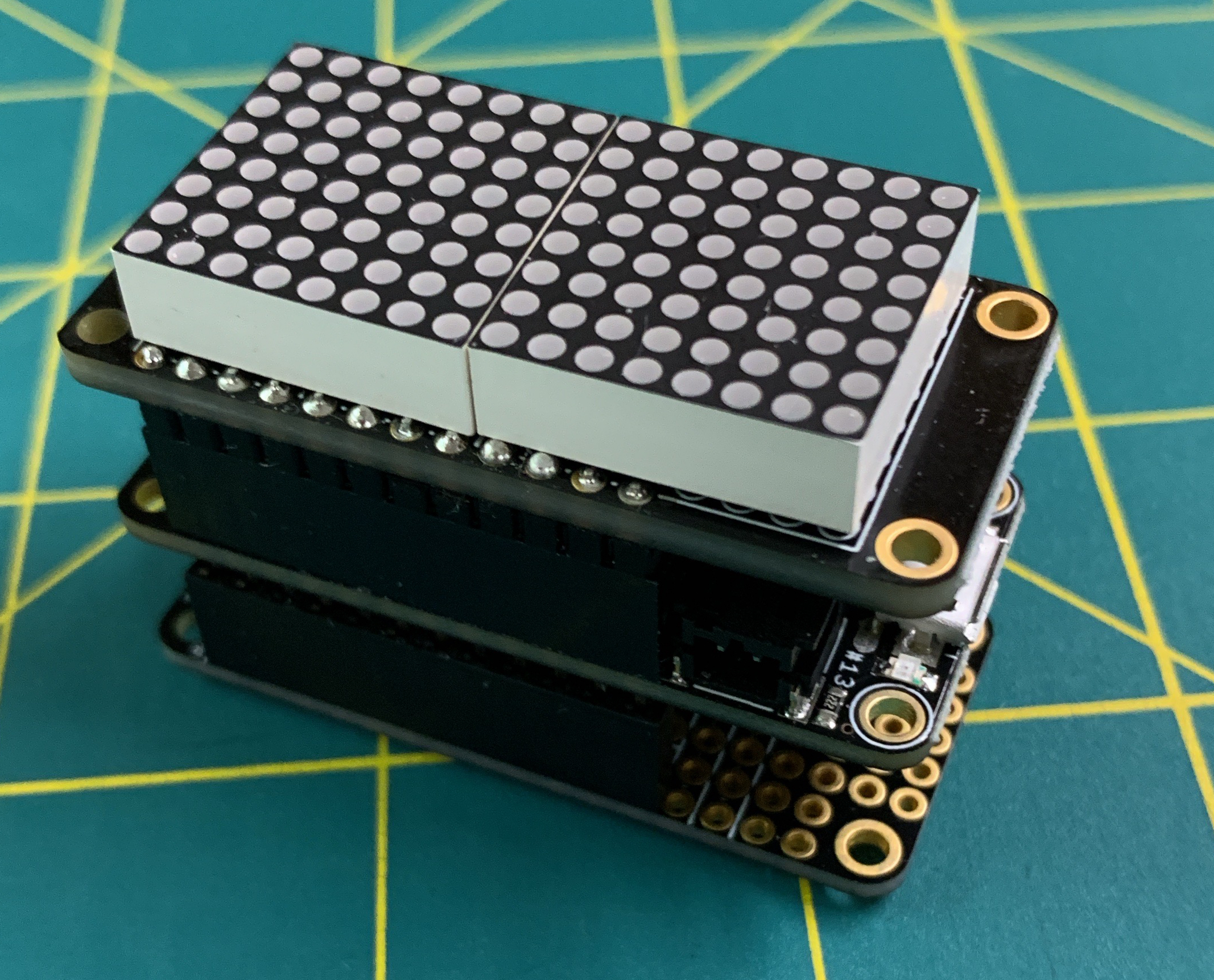
The cutest microcontroller
The brains of the operation is an Adafruit QtPy, chosen for its size, simplicity, and that I really only needed two pins. Also, because I intended to run this off of the USB jack, didn’t really need much more (the neopixels are powered from the GND and 5V pads underneath the QtPy – giving 5V directly from the USB).
Of course, the other special reason is that the QtPy runs CircuitPython, with which I prefer to code my projects. This also helped in the prototyping of the build.
For prototyping, I used a Circuit Playground Express, also from Adafruit. The CPX has 10 neopixels, so I could prototype much of the code – setting up the pixels, the animation, the logic behind it (I’ll get to that). And then all I had to do was copy the code over to the QtPy when everything was hooked up.
About that code
The neopixels at the top are the leaves and the ones at the bottom are the roots lights. For the root lights, I just wanted some white twinkly thing. But for the leaves, I wanted them twinkling the seasons – yellow and white for flowers in the Spring, green twinkling in the Summer, orange and red twinkling in the Autumn, and then off in the Winter (see Summer to Autumn change in GIF above).
That was the easy part. But usually I like to insert something special in the projects I did during this challenge year, give them a wee more meaning. And for this one, I did: dementia.
When leaves forget
This past year I’ve had to spend some time caring for a family member who has dementia, and watch a friend grapple with it in her family. Dementia is a cruel disease, robbing brilliant folks of their memory, their understanding, their awareness. As with other events in my life in the past year, dementia has captured my thoughts of how I could express it in hardware.
Therefore, in my Tree of Life, as the leaves go through the seasons, there is a chance that they forget themselves – they either start wandering the seasons in the opposite direction (say, go from Summer to Spring) or change the length of their season (say, slowing down or speeding up).
The idea is that we would begin to see a single leaf get out of sync with the others. Eventually, all the leaves will fall out of sync as the whole tree gets dementia.
Indeed, testing the progression, indeed the whole set up gets out of sync. I’ve since tweaked the code to slow everything down and be more subtle with the dementia. I have no idea how long things will take, but that’s OK. I’m happy with how it turned out and it’s now hanging in my work space.
Build complete
Also, I’m happy that this was the last one I did. These monthly projects really consumed me whether working on them or not. And the past year was quite eventful for me that there was the added challenge of life (and death) getting in the way. I look forward to non-time-constrained projects. Though, I’ve pondered what my goals for the next year should be. Haha.
In any case, I owe you all a write up summarizing the year, another looking forward to my next year of making (those goals), and I really want to share news from this project that has now run a long time and yielded some interesting insights.
Until next time.